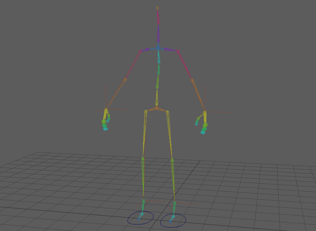
I started the rigging process by following the tutorials on Canvas. I started to create the skeleton for Compton’s character model by starting at the hips and working down the left side. With one side of the skeleton complete, I was then able to mirror the joints to the right side. As all of the joints had been labelled with “L_”, I could task Maya to mirror them to make the right side and replace the “L_” with “R_”.
CREATING CONTROLLERS
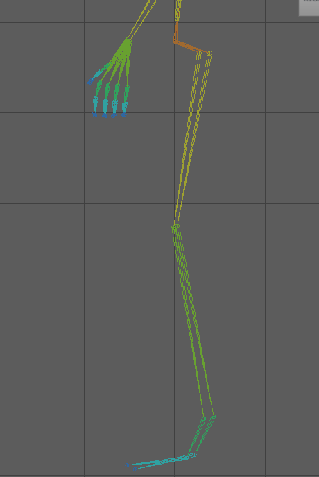
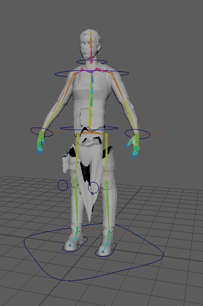
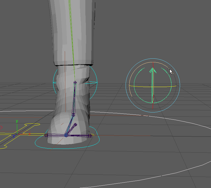
The first controllers I made were the Inverse Kinematic (IK) controllers for the legs, which were created by selecting the leg joint and then the ankle joint. To make the selection easier, a NURBS circle was created and point constrained to the ankle joint to allow me to move the leg. The rotation of the foot was achieved by using an orient constraint to the joint.
One issue that arose from this was that leg IKs were harshly deforming the mesh, snapping inwards after a certain height. Initially, I thought this issue was related to the automatic weights applied by Maya, but after experimentation with changing the weights, it still remained. After seeking advice, I explored using pole vectors, which did not help the issue. When using pole vectors, the upper thigh would rotate to face a direction that was not the direction of the curve.
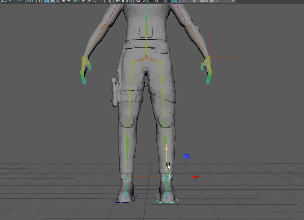
The solution to this issue was changing the joint’s position. Originally, the leg joints were effectively in a straight line which was causing the IK system to move in this manner; By changing the position of the leg joints, the system worked without harshly deforming the mesh.
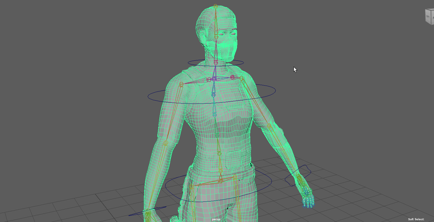
The next controllers to be created were the controllers for both of the arms. The IK system was created by selecting the shoulder joint and then selecting the wrist joint for each side. NURBS curves were created around the respective wrist joints that would allow for easier selection of the IK handles and were constrained to the joints using both point and orient.
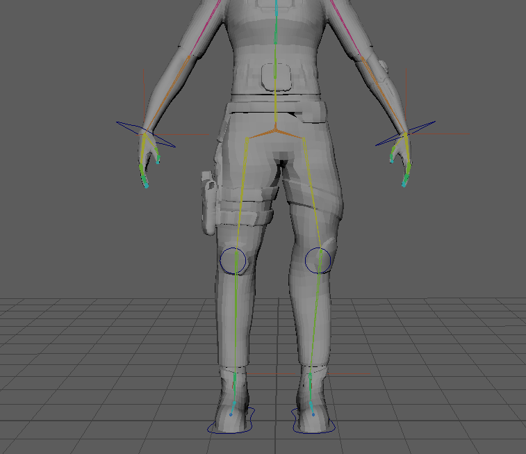
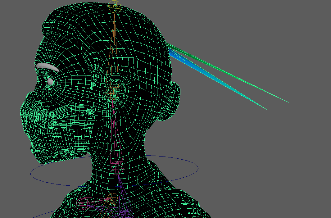
Unfortunately, another issue arose for my character. As the left arm controller was lifted, I noticed that the face was deforming around the left eye. The only cause for this is that a joint in the left arm chain somehow had influence over the face.
WEIGHT PAINTING
Prior to the issue, the majority of my character’s weights only needed minor adjustments. In areas where the mesh was close, such as between the torso and shoulder, the influence was being shared due to the proximity, leading to the torso deforming as the arm moved. This was solved by working through the influence list and removing any influences on a section of the mesh that was not intended.
Upon noticing the issue, I searched through the paint weights and influences list and saw that the face had influence from the joints in the pinky. Upon removing this influence from the head, I then saw that the head was now being influenced by the joints in the thumb and causing the mesh to form spikes.
This issue also affected the weights assigned to other joints. With all of my character’s weights now changed – I decided to reset the weights entirely and follow the inside-out method that had been listed on Canvas. This caused more issues to my character model, with visible issues in the surface of the mesh that worsened when moving.
FOLLOWING A DIFFERENT TUTORIAL
At this stage, I decided to start afresh entirely, as my luck following the Canvas tutorials was seemingly non-existent. I had previously purchased a tutorial series by Nexttut Education called “Introduction to Rigging in Maya 2022” (Nexttut Education, 2022) with the intent to practice my skills.

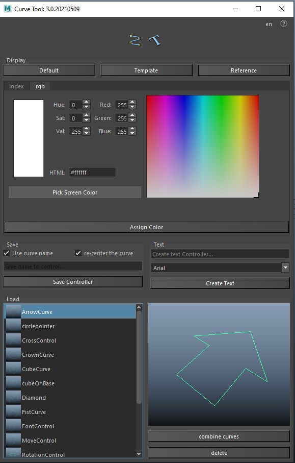
This tutorial followed a similar method of setting up Compton’s rig as the canvas tutorials, starting with the creation of the skeleton and then proceeding to create the foot controllers first. The controllers were created through a free plugin called “Maya Curve Creator v3” from Gumroad (Leijten, 2022); I found this to save time as I was previously creating unique controllers by manipulating the curves, whereas now I could select premade curves and change the colours. I assigned a teal colour for controllers on the left, red for controllers on the right and yellow for any additional controllers, such as facial controls
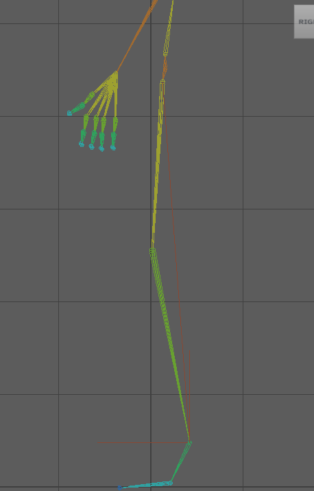
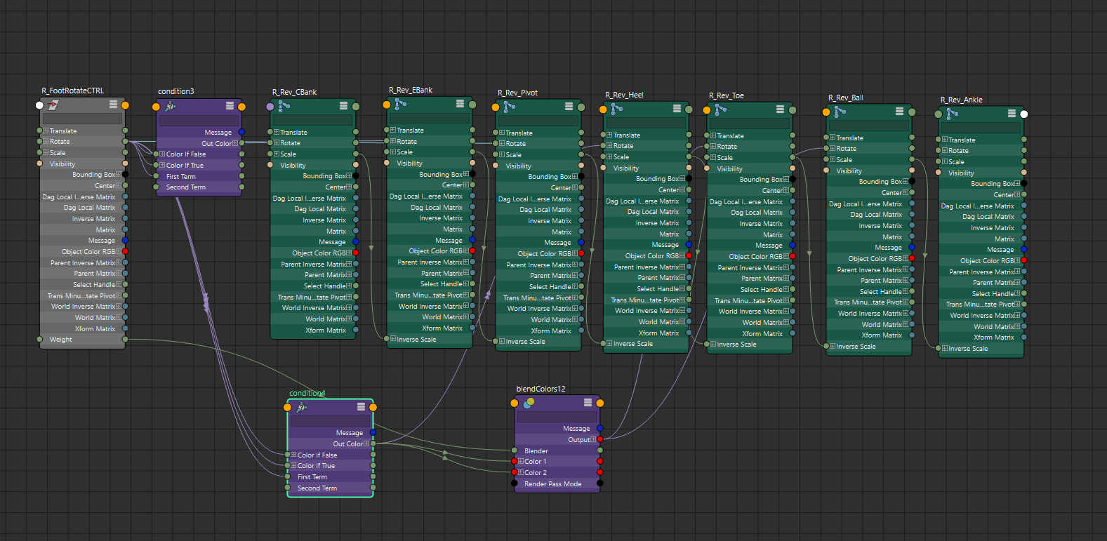
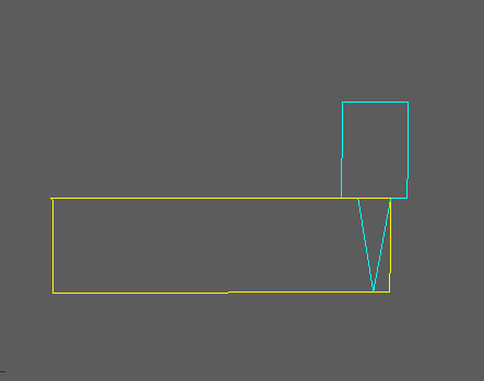
The leg controllers were set up in the same manner as before. A new inclusion to the foot controllers was a bone chain that would create a wider range of motion. This reverse foot control used IKs, but it was slightly different than the IK used to move the leg due to it using a single-chain solver instead of a rotate-plane solver. Additionally, I was able to change where this bone chain was rotating from by changing an attribute, allowing the foot to rotate from the toes rather than from the ankle.
The arm controllers were set up in the same manner as before. I duplicated the original bone chain for both arms and assigned a suffix of “_IK”, as I planned to create a switch that would allow me to toggle between the FK and IK modes. As I now had finished creating the IK Systems, I could then move on to making the Forward Kinematic (FK) systems for the arms. The original bone chain was duplicated again and assigned the suffix of “_FK”, with NURBS curves constrained to the joints.
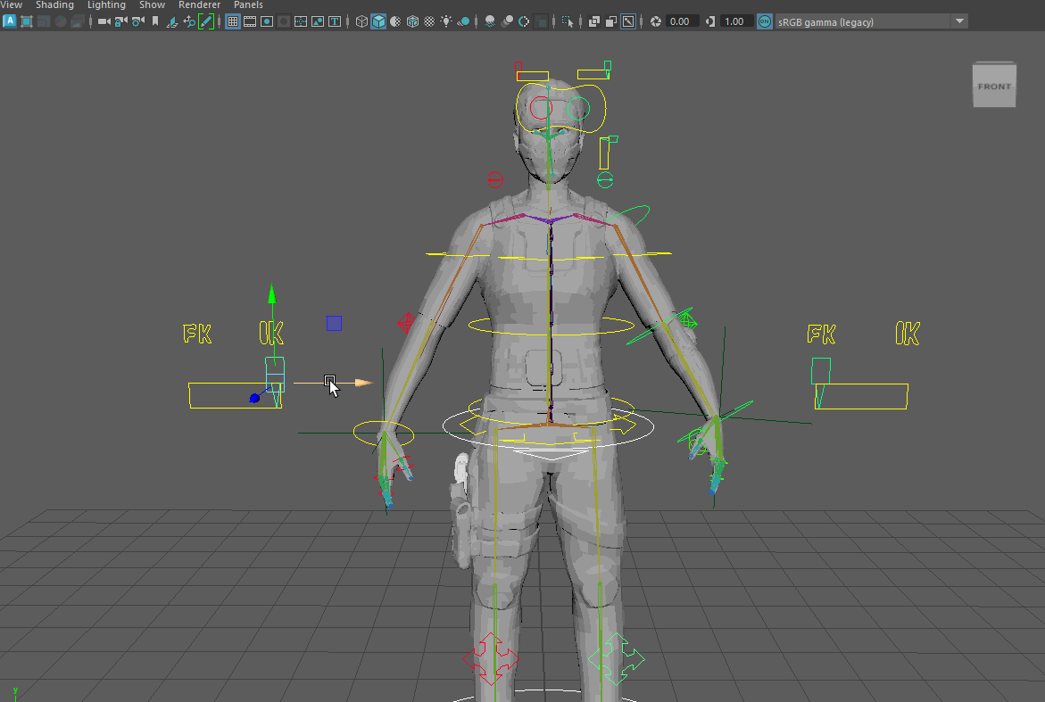
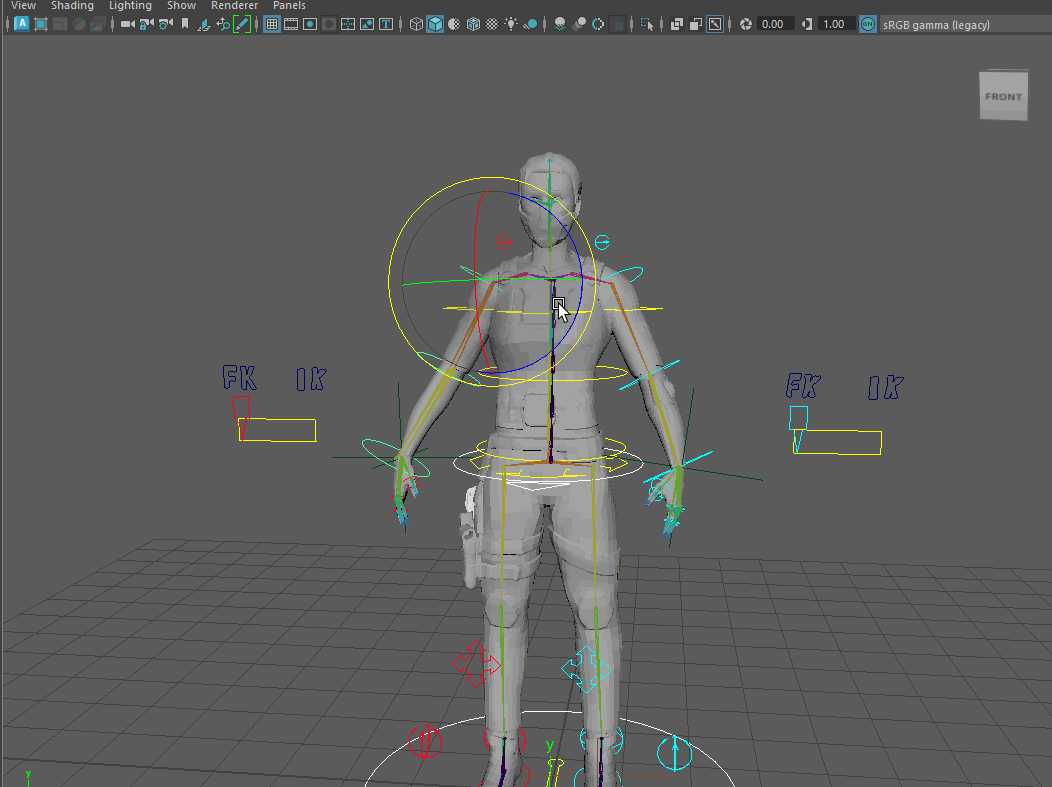
SWITCHING BETWEEN FK AND IK
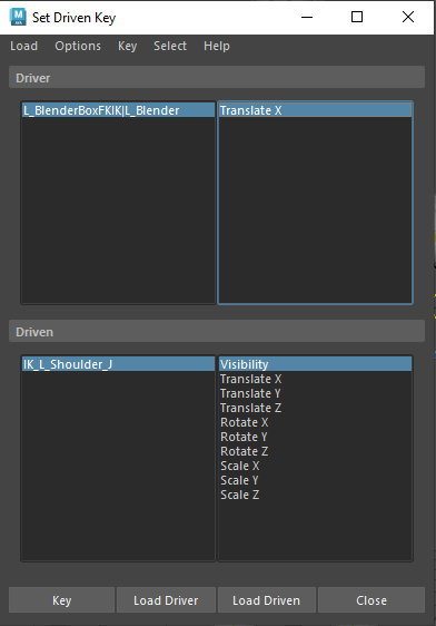
To switch between using FK and IK, I used the Blender Box controller from the plugin, which has a box and a slider component. With this controller, I could toggle the visibility of other controllers through the use of driven keys.
The next step was that when the slider had a value of 1, the FK system would not be visible but the IK would be and vice versa for when the slider had a value of 0. I set up the driven keys so that when I moved the slider (driver) along the X-axis, I was changing the visibility of the chain (driven) to be either off or on.
BUG
I came across an issue when testing the FK/IK switch that was incredibly confusing and took a long time to figure out. When testing that each system worked correctly, I noticed that the right FK would jitter and break. I rebuilt the FK chain a multitude of times in an attempt to solve the problem but with no success.
After seeking assistance, the issue was found. The FK chain was rotating from the clavicle rather than from the shoulder, and with the clavicle having a value of 0.011 on the rotation axes, it was causing the jittery motion. By remaking the clavicle joint, I was able to move the FK chain as intended.
Referenced Material:
Leijten, P. (2022) Maya curve Creator v3. Gumroad. Available online: https://peerke.gumroad.com/l/cuHte
Nexttut Education (2022) Introduction to Rigging in Maya 2022. Udemy. Available online: https://www.udemy.com/course/introduction-to-rigging-in-maya-2022/.